It may sound contrary, but if you take this error into account, 16bit without oversampling is more accurate than 8x-oversampling/20bit.
[diagram4] image noise continuation |
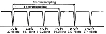
Then what is going to happen if you eliminate the oversampling process? Theoretically, the image noise will be repeated infinitely to higher frequencies (diagram 4), and a conventional answer would be 'it will sound awful'. Really? This has nothing to do with the "Shannon's theorem", nor do I intend to challenge that. Shannon's theorem considers a sampling theory on transmitting an information. I am talking about the perception of the information. That is, if I must say, "the limitation of our auditory sense is a powerful low-pass-filter and the Shannon's theorem is satisfied at the echelon of human auditory perception." My challenge is rather toward those who listen to the sound through theories and oscilloscopes.
Another way of thinking is that, even if humans can't hear it, the equipment that follows can and will be affected by it.
However, 8x-oversampling/digital-filter can only cut off the frequencies between 22.05kHz and 330kHz. Everything beyond 330kHz is all coming through untouched, meaning the degree of effect is determined by how the said equipment reacts to the ingredients beyond 330kHz. My guess is, if 100kHz signwave comes through, there won't be any problem.
Problems of the Digital Filter
The diagram 5 shows the principle of the most popular FIR type digital-filter. The "T" represents a delay circuit for each sampling interval, "a" is for the coefficient multiplier, and "+" is an adder. After delaying the input data, it multiplies with the coefficient, and this process is repeated n times. This 'n' is called the number of taps. The more taps it has, the higher the performance of the filter is supposed to be. The delay mentioned above is not that of a calculating time, but more like a waiting time until the next data arrives.
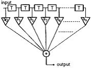
T:adelay circuit
for each sampling interval
a:coefficient multiplier
+:adder
[diagram5]
FIR type digital filter
|
[diagram6]
FIR type digital filter (in case of SM5842)
|
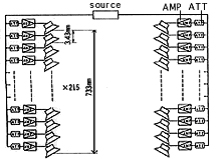
It is rather hard to understand this diagram instinctively. It didn't hit home with me, either. But, one day, it occur to me to replace it with the equivalent of the reproducing hardware system. (diagram 6). The delay circuit is replaced with that of the delay of speed of sound, the multipliers with the attenuators, and the adding is synthesized in the space. The number of the speakers corresponds to that of taps. The diagram shows, as an example, the computation of CD data through the high-performance digital-filter SM5842. The accompanied numbers are the actual sizes in the space when replaced with the hard-ware. Since the sampling frequency of CD is 44.1kHz, each delay time for the 1 x sampling is 22.ms per tap. To achieve 8 x sampling, SM5842 repeats 2 x sampling three times, and each step incorporates the taps of, 169 degrees for 2 x, 29 degrees for 4 x, and 17 degrees for 8 x. The accumulated delay of each step becomes, 1.92ms, 0.16ms, and 0.05ms: total of 2.13ms.
Our auditory sense does the frequency analysis at every 2ms interval, and 2.13ms of delay can be caught by our ear.
If the speed of sound is 346m/s, the total length of the row of speakers becomes 737mm. ( In the diagram, the distance between each speaker is presented by the total delay divided by the total number of taps.)
Now, you can imagine what kind of sound will result from such a system. All the notes coming from the speakers before and behind, will mix, intervene with each other, and spread. I would like to express this expansion of the sound over the time axis as a "diffusion of sound coherence". For example, if an attack of a piano note was not clear enough, as if the felt on the hammer became thicker, you might be hearing this "diffusion of sound coherence"
|
