|

by Ryohei Kusunoki |
||||||
This experience made me wonder if human ears are somewhat insensible to jitter. Whether it has a large or a small amount of jitter is not really an issue. The real problem is the constant fluctuation of the time axis caused by PLL. What is more important is the structure, including the time axis, of jitter, rather than the amount of it. Measurements
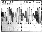
The diagram 10 indicates 1kHz sign wave, -20db. For a comparison, the same waveform through a conventional DAC with digital-filter is shown on the diagram 11. The obvious notches that remained are all formed by components beyond 20kHz and could not be detected by human ear.
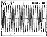
20kHz, 0db is indicated in diagram 12, and that of the comparing DAC in diagram 13. In diagram12, it seems like 22kHz square wave is under amplitude modulation at 4kHz, and no 20kHz can be seen. I am not sure if this is perceived as 20kHz when it is filtered through our auditory sense. I would like to hear opinions from psycho-acoustic professionals. Considering the limit of impairment perception of humans (around 200Hz), however, this amplitude modulation of 4kHz does not need to be worried about at all.
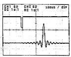
The inpulse response is shown at the diagram 14. The comparing DAC's response is juxtaposed in the same diagram. The one with the inpulse shown downward is that of the non-oversampling DAC. With passive I/V conversion, unless you invert the data somewhere along the way, it comes out as opposite phase. While the comparing DAC shows a familiar waveform, non-oversampling DAC indicates an excellent pulse response. The slant of the top (bottom?) is caused by a low pass filter (160kHz at the time of the measurement). The pre-post echo shown at the bottom picture indicates the "diffusion of sound coherence". I am not saying that you hear this echo as it is, but suggesting that the process which produce this waveform has a problem in itself. If you examine this waveform more closely, undulations of longer term should be observed ahead and behind each echo. |
||||||